Pump Testing
Updated: Mar 16, 2022
Test 1: Determine Effects of Current on Flowrate
To determine whether the pump can meet the imposed 2L/min flowrate constraint, the flowrate was experimentally calculated.
As seen below in Figure 1, a DC power supply was used to power the pump, which will apply the required pressure to displace water from one reservoir to another.

Figure 1: Pump Testing Setup
Test 1 Required Components:
Pump (SFDP1-012-035-21)
DC power supply
3/8" vinyl tubing
Test 1 Procedure:
Fill a reservoir with 750mL of water
Connect the pump 5V and GND lines to DC supply's +ve and -ve lines (CH1)
Adjust the output voltage to 12VDC and output current to 1.8A
Turn on the power supply, and measure the time it takes to displace the 750mL from its reservoir to another. Calculate the flowrate using the known volume and measured time
Repeat step 3-4 with the following DC supply configurations:
12VDC, 2.0A
12VDC, 2.2A
12VDC, 2.4A
The summary of results from Test 1 can be seen in Figure 2 below:
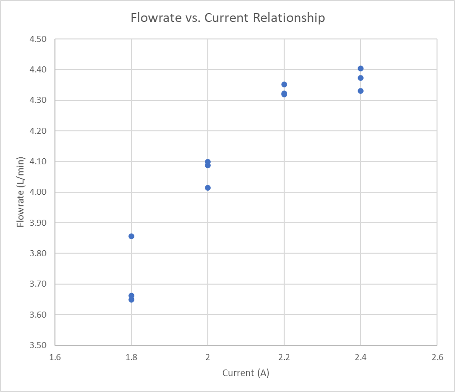
Figure 2: Flowrate Calculations Based on Applied Current
Observations:
Flowrate increases non-linearly depending on current
At 1.8A, the pump does not always start when the DC supply is turned on
At a current of 2.2A+, the flow becomes less laminar and transitions closer to turbulent flow
With these observations in mind, it is determined that the pump meets the 2L/min flowrate spec, and requires 12VDC and 2A for a consistent laminar flow at a flowrate of 4L/min.
Test 2: Determine Effects of Connector on Flowrate and Consistency
To connect reservoir bottles and the 3/8" vinyl tubing, a pour spout was used. To determine the effects of the spout connector on the flow, a test was performed using the settings shown in Table 3. The modified spout was achieved by machining the tapered end of the original spout off, to create a larger, more consistent diameter outlet.
Table 1: Spout Connector Configurations for Testing
 |  | 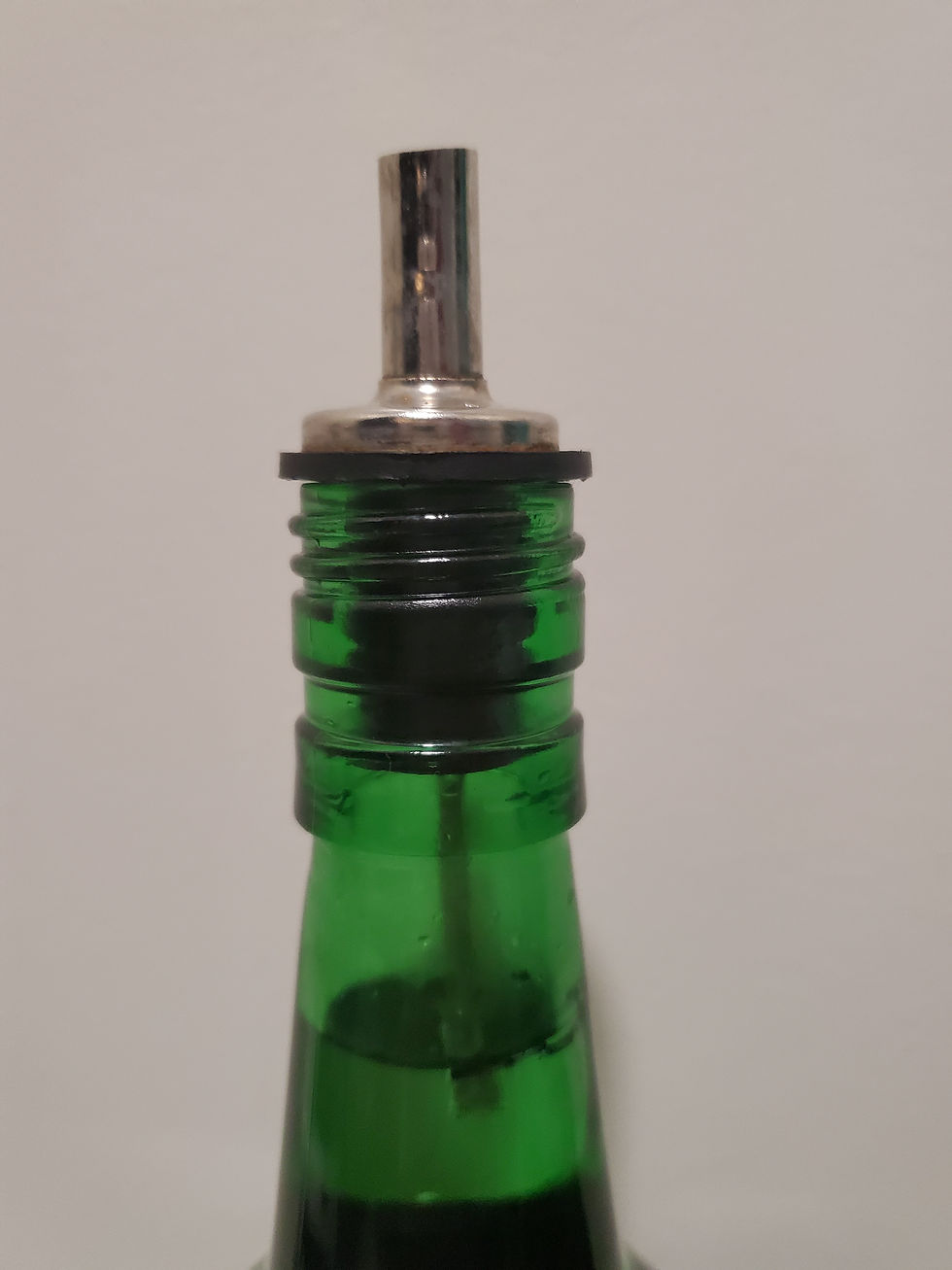 |
No Connector | With Original Connector | With Modified Connector |
Test 2 Required Components:
Pump (insert part number here)
DC power supply
3/8" vinyl tubing
3/8" diameter pour spout
3/8" diameter pour spout (with tapered end machined off)
Test 2 Procedure:
Fill a reservoir with 750mL of water
Connect the pump 5V and GND lines to DC supply's CH1 (+) and (-) lines, respectively
Adjust the output voltage to 12VDC and output current to 2A
Turn on the power supply, and measure the time it takes to displace the 750mL from its reservoir to another. Calculate the flowrate using the known volume and measured time
Repeat step 3-4 with the shown spout configurations as seen in Table 1
The summary of results from Test 2 can be summarized in Figure 3 below:

Figure 3: Effect of Connectors on Flowrate
Observations:
The unmodified spout yields the lowest, least consistent flowrate
No spout configuration yields the highest and consistent flowrate, but presents a problem in connecting to the 3/8" tubing
The modified spout configuration yields slightly lower, but equally consistent flowrate values
Conclusions:
Pump yields acceptable flowrate values at 12VDC and 2A
The modified spout has negligible effects on flowrate (regarding the magnitude and consistency)
Additional Data and Links
Item | Link |
Pump Specifications | http://www.seaflo.com/en-us/product/detail/601.html |
| |

Comments